
How to Size a Current Transformer: Ratio, Burden and Class
Most CT problems start at specification, not installation. Here is a step-by-step method for choosing the ratio, burden and accuracy class for a low-voltage panel — with a worked example. Category: Technical Notes · Tags: current transformers, CT sizing, burden, IEC 61869-2
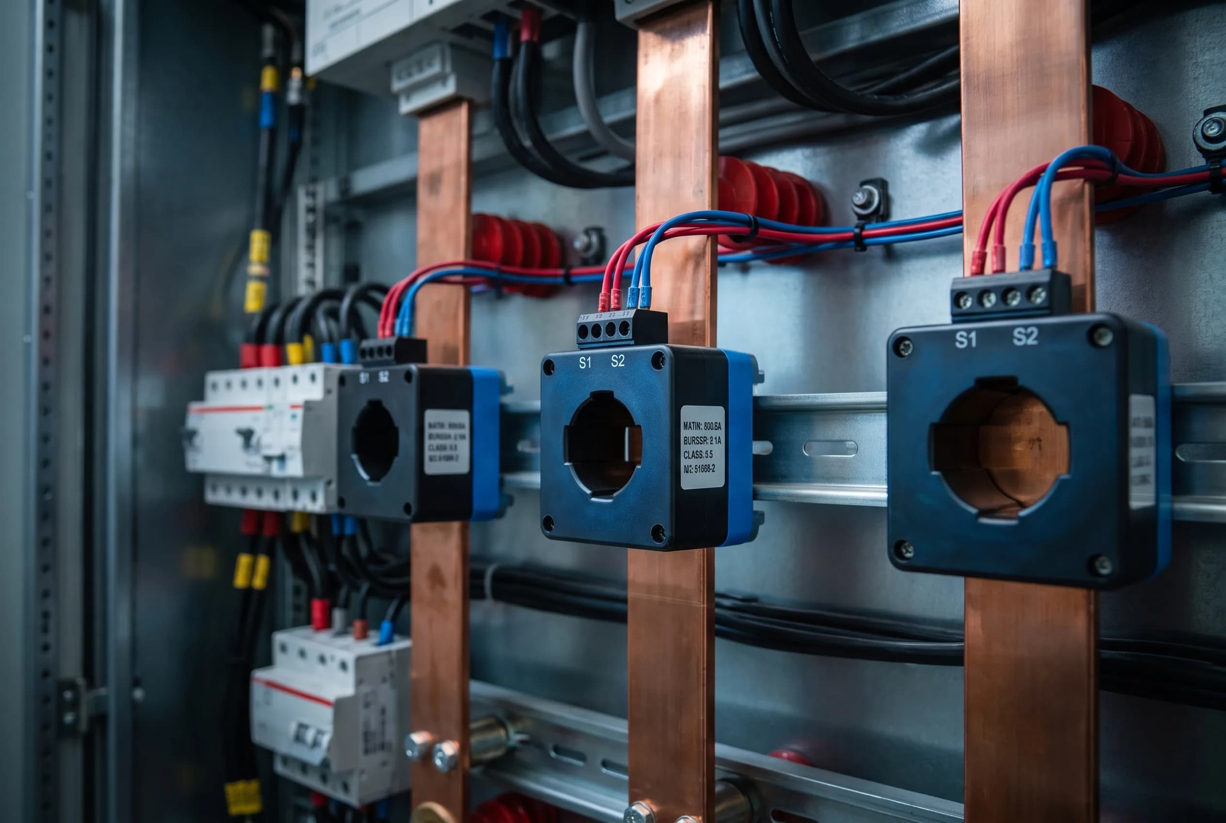
Why CT sizing matters
A current transformer is a measurement device, not a wire. Fit one that is too small and it saturates on overload; too large and the meter reads a fraction of full scale with poor resolution. Either way, the meter is only as accurate as the CT feeding it.
Step 1 — Start from the load current
Take the design current of the feeder (Ib), not the breaker rating alone. The CT primary should sit at or just above the expected continuous load, so the meter operates in the upper part of its range where accuracy is specified.
A common rule: aim for the normal load to fall between 60% and 100% of the CT primary rating. For a 400 A feeder, a 500/5 A CT is usually a better fit than a 1000/5 A unit.
Step 2 — Choose the secondary: 5 A or 1 A
- 5 A is the default in most LV panels and matches the majority of meters and relays.
- 1 A is preferable on long secondary runs or where several instruments are connected, because lead burden falls by a factor of 25 for the same cable.
Stay consistent within a panel. Mixed secondaries create commissioning errors.
Step 3 — Add up the burden (VA)
The CT must drive every device and every metre of cable in its secondary loop. Burden is the sum of:
- The meter or relay burden (from its datasheet, in VA)
- The lead burden: I²R, using the loop length (out and back)
- Any terminals, fuses or test blocks in the loop
Worked example — 400 A feeder, 500/5 A CT, meter 0.5 VA, 6 m run of 2.5 mm² cable:
- Loop length = 12 m
- 2.5 mm² copper ≈ 7.4 Ω/km → 0.089 Ω
- Lead burden = 5² × 0.089 ≈ 2.2 VA
- Total = 2.2 + 0.5 = 2.7 VA
A 5 VA CT covers this with margin. The same loop with a 500/1 A CT drops to about 0.09 VA — one reason 1 A secondaries suit long runs.
Always select a CT with a rated burden greater than or equal to the connected burden. Never size it exactly to the load.
Step 4 — Pick the class for the job
DutyTypical classNotes
Billing / sub-metering
0.5 or 0.2S
0.2S holds accuracy down to 1% of rated current
Panel indication
1.0
Adequate for local displays
Protection
5P10 / 5P20
Accuracy limit factor covers fault current
Mixing duties rarely works. If the same feeder needs metering and protection, specify separate cores or separate CTs.
Step 5 — Check the physical fit
Confirm window size against busbar dimensions, bar-to-bar spacing and terminal clearance. Allow room for the shorting terminal and a visible earth connection on the secondary.
Installation rules that prevent failures
- Never open-circuit a CT secondary while primary current is flowing. Dangerous voltages develop across the open winding.
- Short the secondary before removing a meter, and use a proper test terminal block.
- Earth one side of the secondary at a single point.
- Match the CT ratio setting in the meter to the CT actually installed — a mismatch is the most common cause of impossible readings.
Specification checklist
Before ordering, confirm: primary current, secondary current, rated burden, accuracy class, frequency, window or busbar type, mounting, and short-time thermal rating. Getting these seven right on the purchase order prevents most commissioning callbacks.
Ready To Specify Your Next Project?
Our sales engineers work directly with panel builders and procurement teams to specify the right product, confirm lead times, and coordinate international shipping.